/* This is _120806_in_class_01 renamed
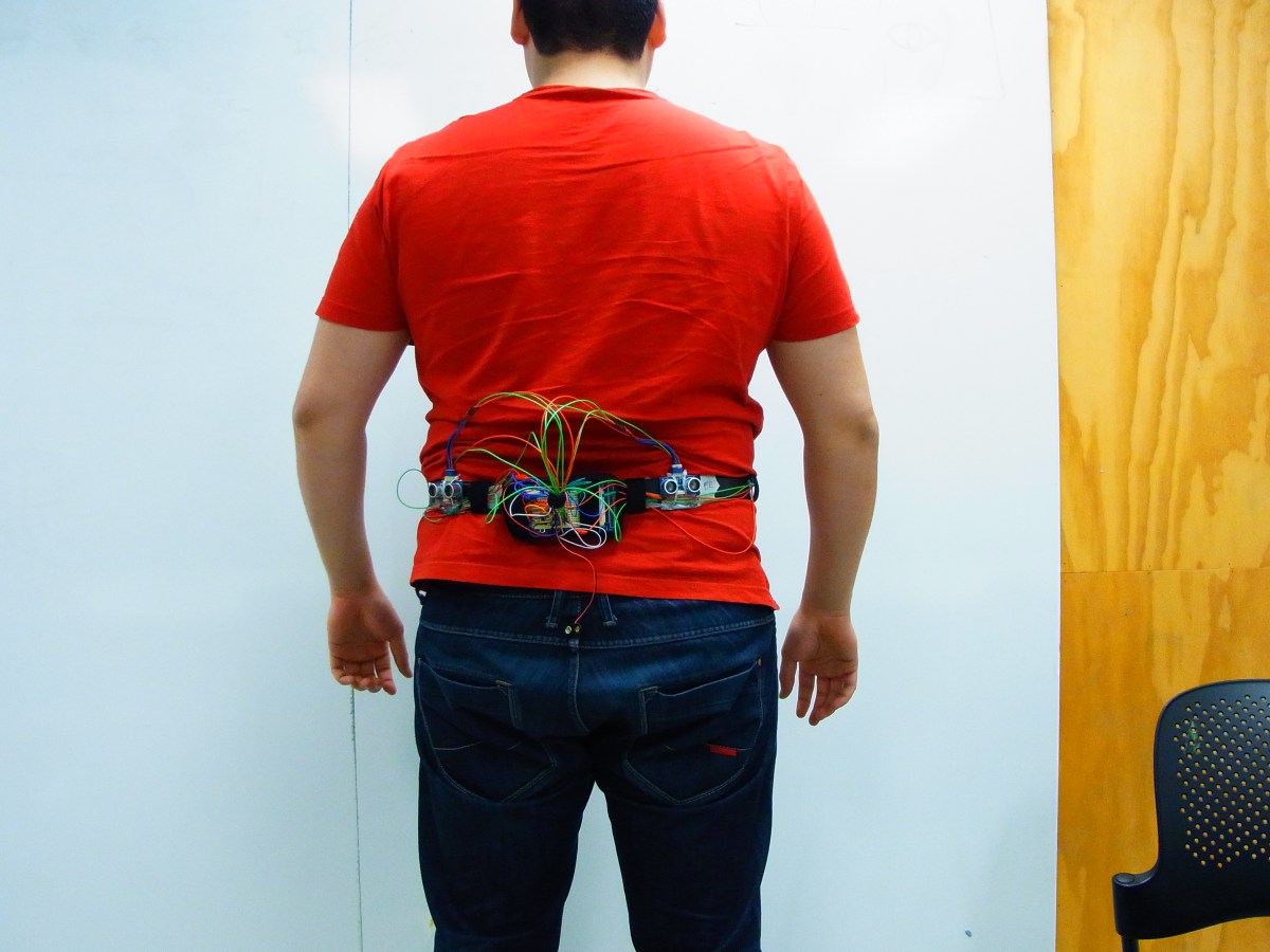
IMRAN SHAMSUL – MAJOR PROJECT – PROJECT ANDERS
*/
// these arrays are looped through, make sure your pinb and motor match.
// so mypin[1] should corrispond to mymotor[1] and so on
int myPins[] = {2,3,4,5};
int myMotors[] = {13,12,11,10};
int howmany = 4;
int maxDistance[] = {20,20,20,20};
int maxPower[] = {255,255,2555,255};
void setup() {
// initialize serial communication:
Serial.begin(9600); // this just means you can output to the serial panel
}
void loop()
{
// establish variables for duration of the ping,
// and the distance result in inches and centimeters:
long duration, cm;
// loop through the pins array, noting theat we’ve set the limit to 5
int i; // define “i” this is used as a count variable
// start a count loop, since you know how many sensors there are, hard code this in the i < NUMBER OF SENSORS bit
for (i = 0; i < howmany; i = i + 1) {
// print out what pin
// Serial.println(myPins[i]);
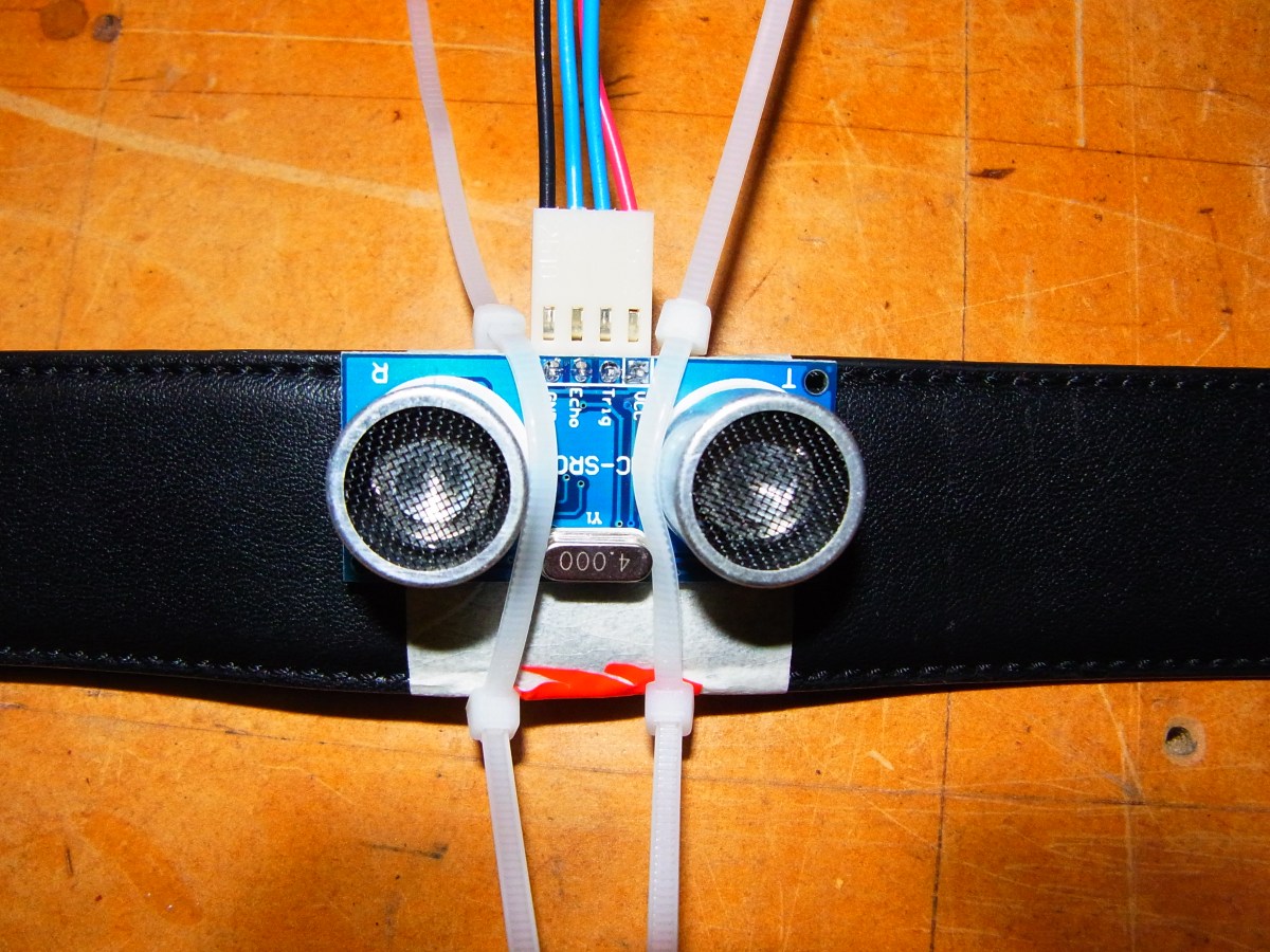
// The PING))) is triggered by a HIGH pulse of 2 or more microseconds.
// Give a short LOW pulse beforehand to ensure a clean HIGH pulse:
// check the pin pMyPin[i]
pinMode(myPins[i], OUTPUT);
digitalWrite(myPins[i], LOW);
delayMicroseconds(2);
digitalWrite(myPins[i], HIGH);
delayMicroseconds(5);
digitalWrite(myPins[i], LOW);
// The same pin is used to read the signal from the PING))): a HIGH
// pulse whose duration is the time (in microseconds) from the sending
// of the ping to the reception of its echo off of an object.
pinMode(myPins[i], INPUT);
duration = pulseIn(myPins[i], HIGH);
// convert the time into a distance
cm = microsecondsToCentimeters(duration);
// Serial.print(inches);
// Serial.print(“in, “);
// inches are for americans, they silly.
Serial.print(myPins[i]);
Serial.print(“-“);
Serial.print(cm);
Serial.print(“cm”);
Serial.println();
// if(cm < 100){
int motorPWM = map(cm,maxDistance[i],0,0,maxPower[i]); //variable map formula relationship
motorPWM = constrain(motorPWM, 0, 255);
analogWrite(myMotors[i],motorPWM);
Serial.print(“motorPWM = “);
Serial.println(motorPWM);
delay(200);
}
// delay(returndelay(cm));
// analogWrite(myMotors[i], 0);
// } else {
// analogWrite(myMotors[i], 0);
// }
// end of the pin loop
// delay(200); uncomment if needed
}
/*
// change to formul
int returnfeedback(int cm){
int motorPWM = map(cm,maxDistance[],0,0,maxPower[]); //variable map formula relationship
motorPWM = constrain(motorPWM, 0, 255);
// if (cm < 5){ // distance
// return 255; // strength
// } else if (cm < 10){
// return 220;
// } else if (cm < 20){
// return 190;
// } else if (cm < 40){
// return 160;
// } else if (cm < 80){
// return 130;
// } else if (cm < 100){
// return 100;
// } else {
// return 0;
// }
Serial.print(“motorPWM = “);
Serial.println(motorPWM);
return motorPWM; //serial print pwm
}
*/
long microsecondsToCentimeters(long microseconds)
{
// The speed of sound is 340 m/s or 29 microseconds per centimeter.
// The ping travels out and back, so to find the distance of the
// object we take half of the distance travelled.
return microseconds / 29 / 2;
}